

Short answer
To design a drip irrigation system, estimate the crop's peak daily water need, choose emitter flow and spacing for your soil, and calculate run time. Then split the field into zones that fit your water supply, size laterals and mains for low pressure loss, add filtration and a pressure regulator per zone, and size the pump for the largest zone.
What does it mean to design a drip irrigation system?
To design a drip irrigation system, you work out how much water the crop needs at peak demand, choose emitters and lateral spacing that deliver it evenly, then size the pipes, valves, pressure regulation, filtration and pump so every emitter receives the right pressure. A good design keeps flow variation between the first and last emitter in a zone within about 10%.
The same method applies whether you are planning how to lay irrigation system pipes in a greenhouse, an orchard block or a vegetable field. Only the numbers change. This guide follows the order an irrigation engineer uses, with a simple worked example, and explains pressure regulators, pressure compensating emitters and how to connect drip line to main line.
How to design a drip irrigation system, step by step
- Collect site data: field map with dimensions and elevations, crop and row spacing, soil texture, water source, available flow and pressure, and a water quality analysis.
- Estimate peak crop water need per plant or per meter of row.
- Choose the emitter type, flow and spacing to suit soil and crop.
- Calculate run time and irrigation interval at peak demand.
- Divide the field into zones so each zone's flow fits the water supply.
- Size laterals, sub-mains and mains for acceptable pressure loss.
- Select pressure regulation, valves and filtration.
- Size the pump for the largest zone flow and total pressure requirement.
- Add fertigation, control and flushing points, then draw the layout of the drip irrigation system.
Step 1: What site information do I need?
Before you build a drip irrigation system, gather:
- Dimensions and elevations. Each 10 m of elevation change alters pressure by roughly 1 bar (about 2.31 ft per psi). Slopes are often the deciding factor between standard and pressure compensating products.
- Soil texture. Sandy soils spread water downward in a narrow column and need closer emitter spacing; clay soils spread water sideways and accept wider spacing and lower flow.
- Water supply. Measure available flow (m³/h or gpm) and static pressure. A well pump's curve or a municipal connection's pressure decides how many emitters can run at once.
- Water quality. Suspended solids, iron, manganese, hardness and algae determine filtration and chemical treatment. Clogging is the most common cause of drip failure.
Step 2: How much water does the crop need?
Peak daily water need is estimated from reference evapotranspiration (ET) for your hottest period multiplied by a crop coefficient and, for trees and wide rows, adjusted for the shaded or wetted fraction. Local extension services and weather networks publish ET values.
Worked example: a tomato field with rows 1.5 m apart, peak crop water use about 6 mm/day. One meter of row covers 1.5 m², so it needs about 6 × 1.5 = 9 L per day. Allowing for roughly 90% application efficiency, plan for about 10 L per meter of row per day.
Step 3: Which emitter flow and spacing should I choose?
Common emitter flows are about 1, 2, 4 and 8 L/h. In US units, the 1 gph drip emitter (about 3.8 L/h), the 2 gph drip emitter (about 7.6 L/h) and the 4 gph drip emitter (about 15 L/h) are the standard sizes, with 1/2 and 1/4 gph emitters for pots and substrate. Inline drip line typically has emitters every 20–50 cm for row crops and 50–100 cm for orchards.
| Soil texture | Typical emitter flow | Typical spacing on drip line | Notes |
|---|---|---|---|
| Sand, loamy sand | 1.6–2.2 L/h (about 0.4–0.6 gph) | 20–30 cm | Short, frequent pulses to avoid deep drainage |
| Loam, silt loam | 1–2.2 L/h (about 0.25–0.6 gph) | 30–40 cm | Most flexible; wide range works |
| Clay loam, clay | 0.6–1.6 L/h (about 0.16–0.4 gph) | 40–60 cm | Low flow prevents surface ponding and runoff |
| Trees (any soil) | 2–8 L/h per emitter, several per tree | 50–100 cm or point emitters | Wet roughly a third to a half of the canopy area |
| Substrate / pots | 1–4 L/h per plant | One stake or emitter per plant | Use pressure compensating, anti-drain emitters |
These are starting points. Do a simple wetting test in your own soil if you can.
Example continued: loam soil, drip line with 1.6 L/h emitters every 30 cm gives about 3.3 emitters per meter, or about 5.3 L/h per meter of row.
Step 4: How long should the system run?
Run time equals daily need divided by application rate. In the example: 10 L ÷ 5.3 L/h ≈ 1.9 hours per day at peak. You might split that into two or three pulses, especially on light soils. Extension guidance commonly advises leaving spare time in the day, for example not planning more than about 16–18 hours of total operation, so the system can catch up after a breakdown.
Step 5: How do I divide the field into zones?
A zone (or block) is the area that irrigates at one time behind one valve. Its flow must fit the water supply.
Example continued: a 1 ha field with 1.5 m rows holds about 6,700 m of row. At 5.3 L/h per meter, the whole field would need about 35 m³/h. If the well delivers 15 m³/h, split the field into three zones of about 12 m³/h each. Three zones at 1.9 hours each need under 6 hours per day, which leaves plenty of spare capacity.
Keep zones on similar elevation and soil, and keep different crops or growth stages on separate valves.
Step 6: How long can laterals be, and how do I size pipes?
Pressure falls along each lateral because of friction, and rises or falls with elevation. Maximum lateral length depends on pipe diameter, emitter flow and spacing, inlet pressure and slope, so always use the manufacturer's length tables. As rough orders of magnitude on flat ground, thin 16 mm drip tape is often run 100–200 m, 16 mm drip line 80–150 m depending on emitter flow, and 20 mm drip line longer. Pressure compensating drip line allows longer runs.
For sub-mains and mains, a common rule of thumb keeps velocity at or below about 1.5 m/s (around 5 ft/s) to limit friction loss and water hammer. For the distribution network you can use PE pipe, PVC or lay-flat hose. Our guide to drip tape vs. drip line explains lateral choices.
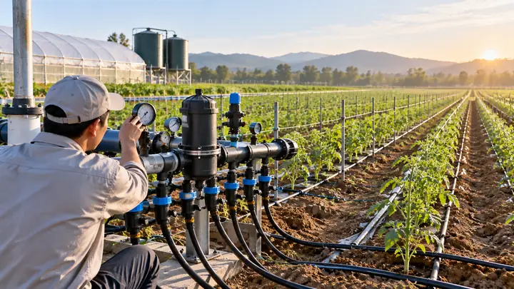
How to connect drip line to main line
- Drill or punch a clean hole in the PE or PVC sub-main using the tool size specified for the takeoff.
- Insert a grommet and barbed takeoff, or use a saddle with a start connector on rigid PVC.
- Flush the sub-main before connecting laterals.
- Push the drip line onto the barbed or compression connector and lock it, then add an end closure or flush valve.
Choose start connectors with a mini-valve if you want to isolate single rows. The drip emitters and fittings guide covers connector types.
Step 7: What pressure does drip irrigation need?
Typical psi for drip irrigation is lower than for sprinklers:
- Drip tape: often about 0.5–1 bar (roughly 8–15 psi).
- Non-compensating drip line: often about 0.5–2 bar (roughly 8–30 psi), depending on the product.
- Pressure compensating emitters and drip line: commonly regulate between about 0.5–1 bar at the low end and 3.5–4 bar at the high end; check the data sheet.
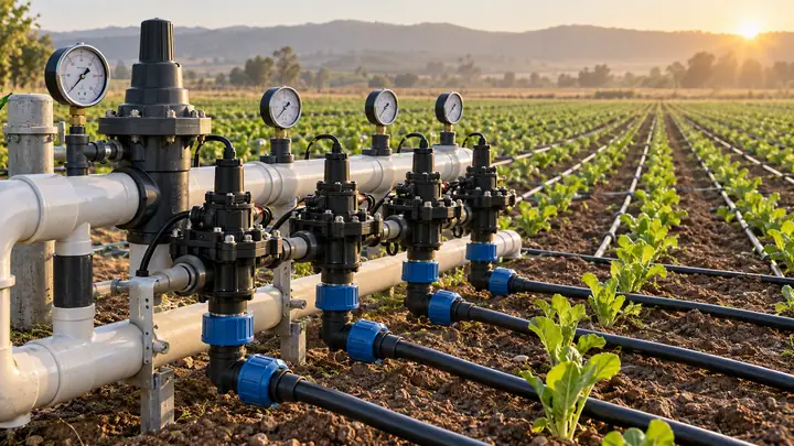
Water pressure for drip irrigation from a well or mains is often 3–5 bar or more, which is too high for tape and many fittings. That is why each zone usually gets a pressure regulator for the irrigation system.
Pressure reducer for drip irrigation: preset or adjustable?
A pressure reducer for drip irrigation lowers and stabilizes downstream pressure. Preset regulators are cheap and simple and suit small zones. Adjustable regulators, or pressure-reducing hydraulic valves, are used at the head of larger zones and on sloping fields where each block needs a different setting. A water pressure regulator for drip irrigation should be installed after the filter and zone valve, sized for the zone's flow range, not the pipe diameter. On slopes, divide the field into sub-units each with its own regulator, or use pressure compensating drip line.
When do pressure compensating drip emitters pay off?
Pressure compensating emitters deliver nearly the same flow across a wide pressure range. Use pressure compensating drip emitters or pressure compensating drip line when:
- The field has noticeable slope or undulations.
- Laterals are long and you want fewer sub-mains.
- Growing in substrate, pots or vertical systems where each plant must get the same volume.
They cost more, so on flat, short runs standard turbulent-flow emitters are often fine.
Step 8: How do I choose filtration and size the pump?
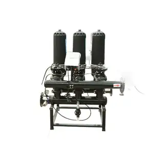
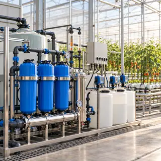
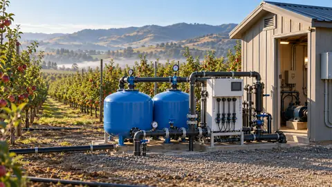
Filtration comes first in the head unit. Sand media filters handle surface water with algae; disc and screen filters suit cleaner well water. Final filtration for drip is commonly around 120–150 mesh, and finer for some tape products. Units such as an automatic gear disc filter self-clean by backwashing. See our irrigation filters guide.
Pump pressure must cover emitter pressure, friction in laterals, sub-mains and mains, losses in valves and filters (assume a dirty filter), injector losses and elevation. Pump flow must match the largest zone. An engine-pump digital irrigation system combines pump, control and dosing for sites without grid power.
Step 9: Add fertigation, control and flushing
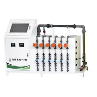
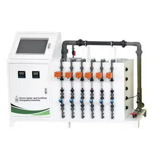
- Fertigation: size injectors from zone flow and stock ratio; see how to size a fertigation system. A smart fertigation machine with dosing pump handles dosing and zone scheduling together.
- Control: a controller with flow monitoring makes it easy to run several short cycles; see smart irrigation controllers.
- Backflow prevention wherever fertilizer is injected.
- Air/vacuum relief valves at high points and at the head of each zone, to prevent soil being sucked into emitters when lines drain.
- Flush valves or a flush manifold at the end of laterals.
How to set up and commission a drip system
- Lay mains and sub-mains, flush them clean, then connect laterals.
- Run water with the ends of laterals open until it runs clear, then close them.
- Set each pressure regulator and check pressure at the zone inlet and the end of the farthest lateral.
- Measure emitter flow with a container and stopwatch at several points; flows should be within about 10% of each other.
- Record baseline flow and pressure for each zone, so later changes reveal clogging or leaks.
- Program the controller and fertigation, then check the first cycles in person.
Common drip design mistakes
- Laterals longer than the manufacturer allows, so the far end underwaters.
- No pressure reducer, so tape bursts or fittings pop off.
- Undersized filtration, or no filter after the fertilizer injection point.
- Zones too large for the pump or well.
- Running laterals uphill on slopes instead of across the slope or downhill.
- No flushing points, so sediment collects at lateral ends.
Mars Vertical Farm builds filtration, fertigation and pump units with OEM/ODM options for distributors and contractors. Browse the irrigation and fertigation range, or send us your field layout, crop and water test to get a drip layout and equipment quotation.